
Part and mould design: Designcenter NX, Mold Wizard, Moldex3D
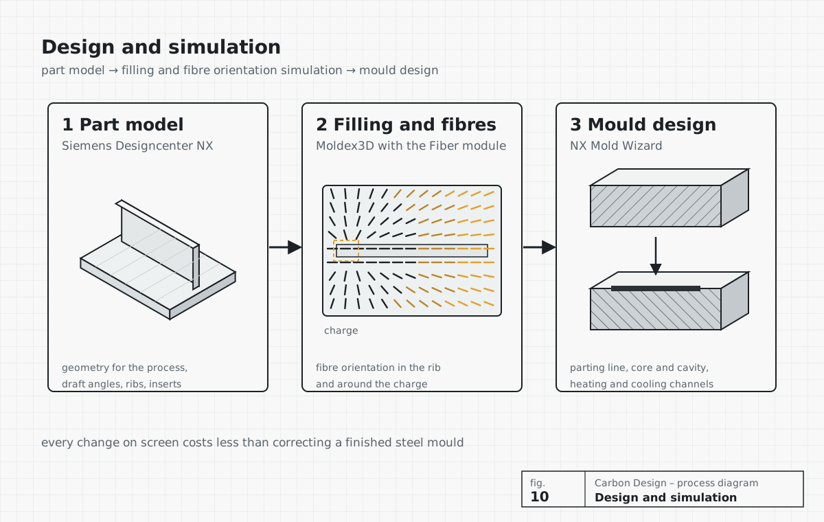
We design the part, the mould and the process with one chain of tools. The model and documentation are made in Siemens Designcenter NX, the mould in NX Mold Wizard, and mould filling and fibre orientation are checked in a Moldex3D simulation with the Fiber module – before any steel is cut.
Software we use
Tools and what you get from them
We deliver results in formats your toolmaker and design team can open.
| Tool | What we use it for | Result for you |
|---|---|---|
| Siemens Designcenter NX | Solid and surface modelling of the part for the chosen process, ply layup, inserts and joints, 2D documentation with tolerances. | 3D model (NX, STEP, Parasolid) and manufacturing drawings |
| NX Mold Wizard | Mould design: draft and undercut checks, parting line and surface, core and cavity, shrinkage, heating and cooling channels, mould base and standard parts. | Mould model ready for the toolmaker |
| Moldex3D with the Fiber module | Simulation of mould filling and of the orientation, length and distribution of fibres in fibre-reinforced materials, including SMC and BMC compression moulding; anisotropic shrinkage and warpage. | Report with results, risks and recommended changes to the geometry, charge or mould |
Why we simulate fibre orientation
In chopped-fibre materials – forged carbon (C-SMC), BMC, fibre-reinforced plastics – the fibres flow with the resin. Their orientation changes during moulding and decides the strength, stiffness and warpage of the finished part.
A Moldex3D simulation with the Fiber module shows how the material will fill the mould and how the fibres will align – in ribs, around holes and inserts, and where flow fronts meet. We then change the geometry, the charge placement or the mould before the toolmaker starts cutting steel. Every change on screen costs less than correcting a finished mould.
- Areas with unfavourable fibre orientation in loaded zones
- Risk of short shots, flash and air traps
- Anisotropic shrinkage and warpage of the part
- Effect of the charge placement and press force on the result
How a design project runs
We use the same chain for a new part and for a review of an existing mould.
- Part model in Siemens Designcenter NX for the chosen process – draft angles, radii, thicknesses, inserts.
- Moldex3D simulation with the Fiber module: filling, fibre orientation, shrinkage and warpage.
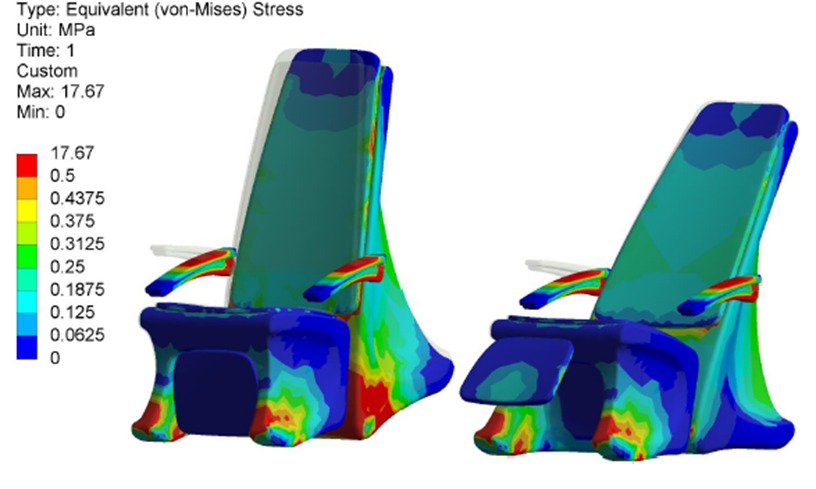
- Changes to the geometry and charge based on the simulation and FEM results.
- Mould design in NX Mold Wizard: parting, core and cavity, heating and cooling, mould base.
- Documentation for the toolmaker and supervision of mould making.
- Trial batch and comparison of the parts with the simulation results.
From our projects
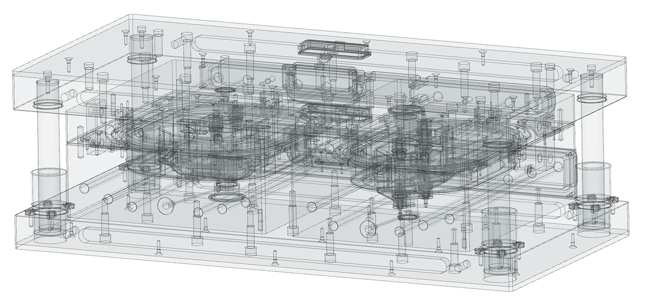
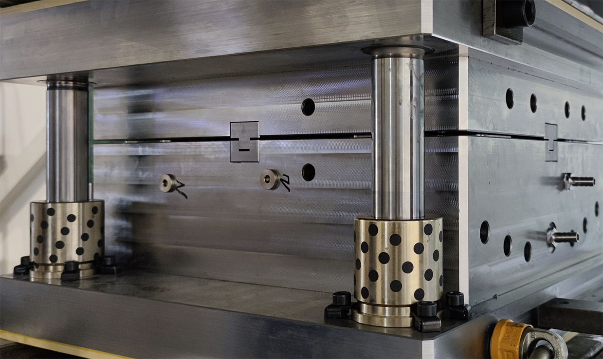
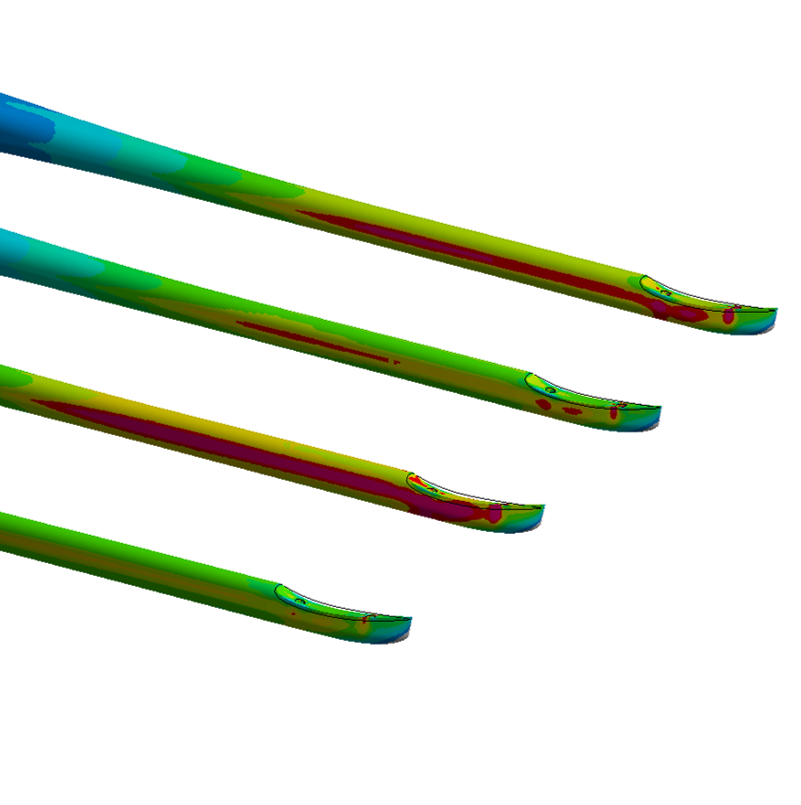
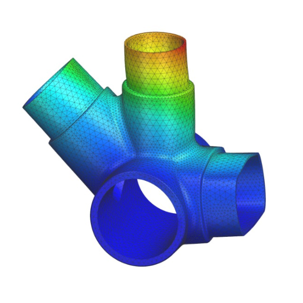
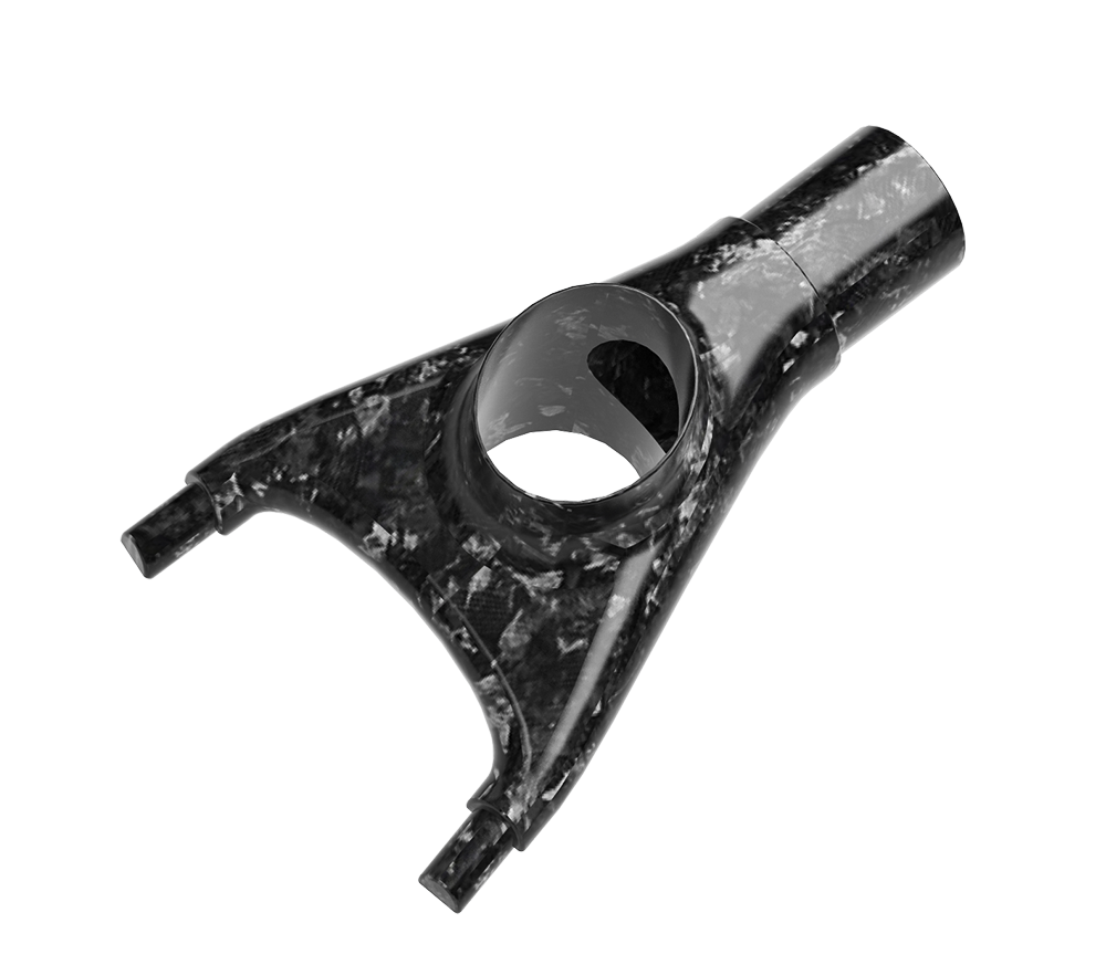
Models, FEM analyses and moulds from projects we can show publicly.
Part design for production
Redesign of a metal or plastic part for composites – for a specific process and volume.
Mould design
Moulds for C-SMC and prepreg compression moulding, RTM moulds and lamination moulds – with a model ready for the toolmaker.
Simulation for your project
A Moldex3D simulation of your existing model or mould, with a report and recommended changes.
Mould review before you order
A check of the feasibility and risks of a mould design before you order it from a toolmaker.
Questions and answers
Which software do you use for parts and moulds?
Parts and documentation in Siemens Designcenter NX, moulds in NX Mold Wizard, and mould filling and fibre orientation in Moldex3D with the Fiber module.
What does a Moldex3D Fiber simulation give me?
It shows how a fibre-reinforced material will fill the mould and how the fibres will align. It reveals zones with unfavourable fibre orientation, the risk of short shots and the warpage of the part – before a steel mould exists.
Can you do only the simulation or only the mould design?
Yes. Each service is available on its own – also for a project prepared by your team or another company.
Which file formats do you accept and deliver?
Native Siemens NX / Designcenter files (.prt) work best – without losing history and parameters. We also accept Parasolid (.x_t, .x_b), STEP, IGES and 2D drawings in PDF and DWG, and deliver results in the same formats.
Do you design RTM and lamination moulds, not only compression moulds?
Yes. In NX Mold Wizard we design moulds for C-SMC and prepreg compression moulding, RTM and light RTM moulds, and moulds for lamination and infusion.
Have a drawing or just an idea? We will tell you how to make it.
Tell us what the part has to do, how many you need and what the requirements are. We will reply with a proposed process, material and next steps – with no obligation, under NDA if needed.